Custom Enclosures Design for Electronics and Electrical Applications
Most electronics start life on a bench — a bare PCB connected to a power supply, doing what it’s supposed to do. The enclosure comes later. And that’s often where the problems begin, because an enclosure is not just a box that goes around the electronics. It’s a structural, thermal, electromagnetic, and user-interface solution that has to be designed, engineered, and manufactured to the same standard as the electronics it contains.
Table of Contents
At Bluefrog Design, based in Leicestershire, we design custom enclosures for electronics across industrial, consumer, and medical sectors. This article covers the decisions that actually determine whether an enclosure works in production and in the field — not just on the workbench.
Start with the electronics, not the enclosure
The most common mistake in enclosure design is treating it as a separate exercise from the electronics development. The enclosure’s internal dimensions, mounting points, cable routing, ventilation, and access panels are all determined by the PCB layout, component heights, connector positions, and thermal characteristics of the electronics. If the enclosure design starts before the electronics architecture is stable, it will need redesigning once the board layout changes — and it will change.
The right starting point is a clear understanding of the electronics package: board dimensions, component clearances, connector locations and types, heat-generating components and their thermal requirements, and any EMC shielding requirements. The enclosure is then designed around this, not the other way around.
That said, the enclosure and electronics should develop in parallel, with the mechanical and electrical teams communicating continuously. PCB layout decisions affect enclosure geometry, and enclosure constraints affect PCB layout. Neither can be finalised in isolation.
Material choice: what drives the decision
The material for an electronics enclosure is not an aesthetic choice — it’s an engineering decision driven by the application requirements.
Sheet metal (steel or aluminium)
Provides natural EMC shielding when properly grounded and bonded. Robust in industrial and outdoor environments. No tooling investment for fabricated construction, making it cost-effective at lower volumes. Aluminium offers weight savings and better thermal conductivity for passive cooling. Steel provides greater strength and lower material cost. Sheet metal enclosures are typically fabricated from flat sheet — laser-cut, brake-formed, and welded or fastened — which allows design changes without scrapping tooling.
Injection moulded plastic
Offers design freedom for complex geometries, integrated features (bosses, snap-fits, cable guides), and a wide choice of surface finishes. Requires tooling investment that only makes commercial sense above a certain production volume. Does not provide EMC shielding; inherently — conductive coatings, metalised films, or internal shielding cans may be needed. Material selection must account for flammability rating (UL 94), UV stability if used outdoors, and chemical resistance for the intended environment.
Die-cast aluminium
Combines the EMC shielding properties of metal with the geometric complexity achievable through casting. Good thermal performance. Suitable for rugged environments. Tooling costs are significant, so this option is typically reserved for medium to high volume products or applications where the performance requirements justify the investment.
Ingress protection: designing for the environment
The IP rating defines how well the enclosure protects the electronics against solid particles and water. The required rating depends entirely on where the product will be used.
IP20 is sufficient for indoor, controlled environments like office or laboratory settings. IP54 is typical for industrial environments where dust and splashing water are present. IP65 and above are required for outdoor or washdown environments. IP67 is needed where temporary submersion is possible.
The IP rating is not just a specification — it’s a design constraint. Achieving IP65 or above requires gaskets on every sealing face, cable glands or sealed connectors for all cable entries, no unsealed ventilation openings (which conflicts with thermal management requirements), and careful management of tolerances on mating surfaces to maintain seal compression.
Every step up in IP rating adds cost and design complexity. Specifying a higher rating than the application requires wastes money. Specifying a lower rating than the application requires causes field failures. Getting this right is a core part of the engineering process.
Thermal management
Electronics generate heat. The enclosure must remove that heat or manage it to keep component temperatures within their operating limits. How this is achieved depends on how much heat is generated, the ambient temperature range, and the IP rating.
Passive cooling through conduction and natural convection is the simplest approach — heat conducts through the enclosure walls and dissipates to the surrounding air. This works for low-power electronics in moderate environments. Metal enclosures are inherently better at this than plastic ones because of their higher thermal conductivity. Aluminium is approximately five times more conductive than steel.
Ventilated enclosures with louvres or mesh openings allow airflow across heat-generating components but reduce the achievable IP rating. Forced convection using fans increases airflow and cooling capacity but adds noise, power consumption, and a component that will eventually need replacing.
For sealed enclosures (IP65 and above), thermal management becomes more challenging. Options include designing the enclosure walls as heat sinks with external fins, using internal heat spreaders to distribute thermal load, or specifying components rated for higher operating temperatures to increase the thermal budget.
EMC: keeping interference in and out
Electromagnetic compatibility is a compliance requirement for any electronic product sold in the UK (UKCA) and EU (CE). The enclosure plays a significant role in meeting EMC standards by shielding the electronics from external electromagnetic interference and preventing the electronics from radiating interference that could affect other equipment.
Metal enclosures provide natural shielding, but only if they are properly bonded and grounded. Seams, joints, and access panels all present potential leakage paths. Conductive gaskets, EMC finger strips, and controlled grounding points are used to maintain shielding continuity across joints.
Plastic enclosures require additional measures: conductive paint or vacuum-metallised coatings on internal surfaces, discrete shielding cans over sensitive or noisy components, or the use of conductive plastic compounds. Each approach adds cost and complexity, which needs to be weighed against the advantages plastic offers in terms of design freedom and weight.
EMC is not something that can be addressed after the enclosure is designed. The shielding strategy needs to be considered from the start, because it affects material choice, joint design, cable entry points, and the internal layout of the electronics.
Designing for assembly and service
An enclosure that is difficult to assemble costs more to manufacture. An enclosure that is difficult to service costs more to support. Both need to be considered during design.
For assembly, the design should allow the electronics and wiring to be installed in a logical, sequential process. Cable routes should be clear and unobstructed. Fixings should be accessible with standard tools. Components that need to be installed in a specific order should be positioned so the sequence is obvious. Where possible, connectors should be accessible from outside the enclosure so that factory testing can be performed before the enclosure is fully closed.
For service, consider which components are most likely to need replacement or maintenance over the product’s life. These should be accessible without removing the entire enclosure or disturbing other components. Removable panels, hinged covers, and quick-release fixings can all improve serviceability without compromising the enclosure’s protective performance. These are the kinds of decisions that define good design for manufacture.
Manufacturing process and cost
The choice of manufacturing process determines the cost profile of the enclosure:
Sheet metal fabrication has no tooling cost, making it cost-effective for low to medium volumes (typically under 1,000-2,000 units). Design changes can be implemented quickly by modifying the flat pattern files. Unit cost decreases with volume but at a slower rate than moulded parts.
Injection moulding requires significant tooling investment (typically £8,000 to £50,000+ per tool depending on complexity), but unit cost is low at volume. This makes sense when production quantities justify the tooling amortisation — usually above 2,000-5,000 units depending on part size and complexity. Design changes after tooling are expensive.
Die casting sits between the two in terms of tooling cost and is typically used where the mechanical and thermal properties of cast aluminium are specifically required.
The manufacturing process decision should be made during concept design, not after the enclosure shape has been finalised. Each process has different rules about achievable geometries, wall thicknesses, draft angles, and joint methods. Designing for the wrong process creates problems that are expensive to fix. For a more detailed look at process selection, see Designing Products for Manufacture in 2026.
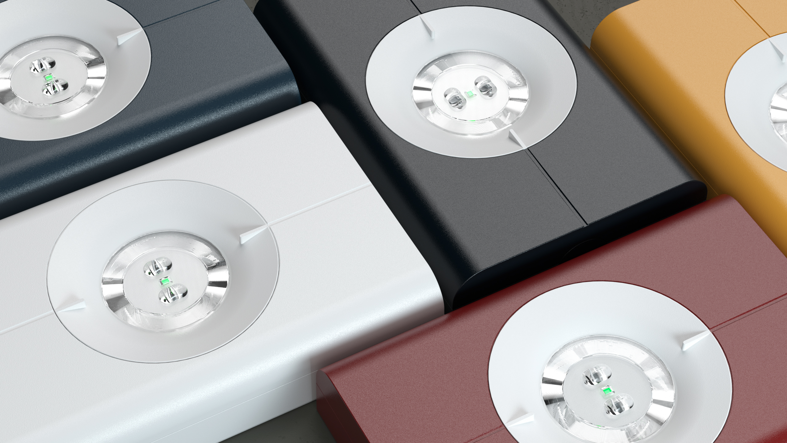
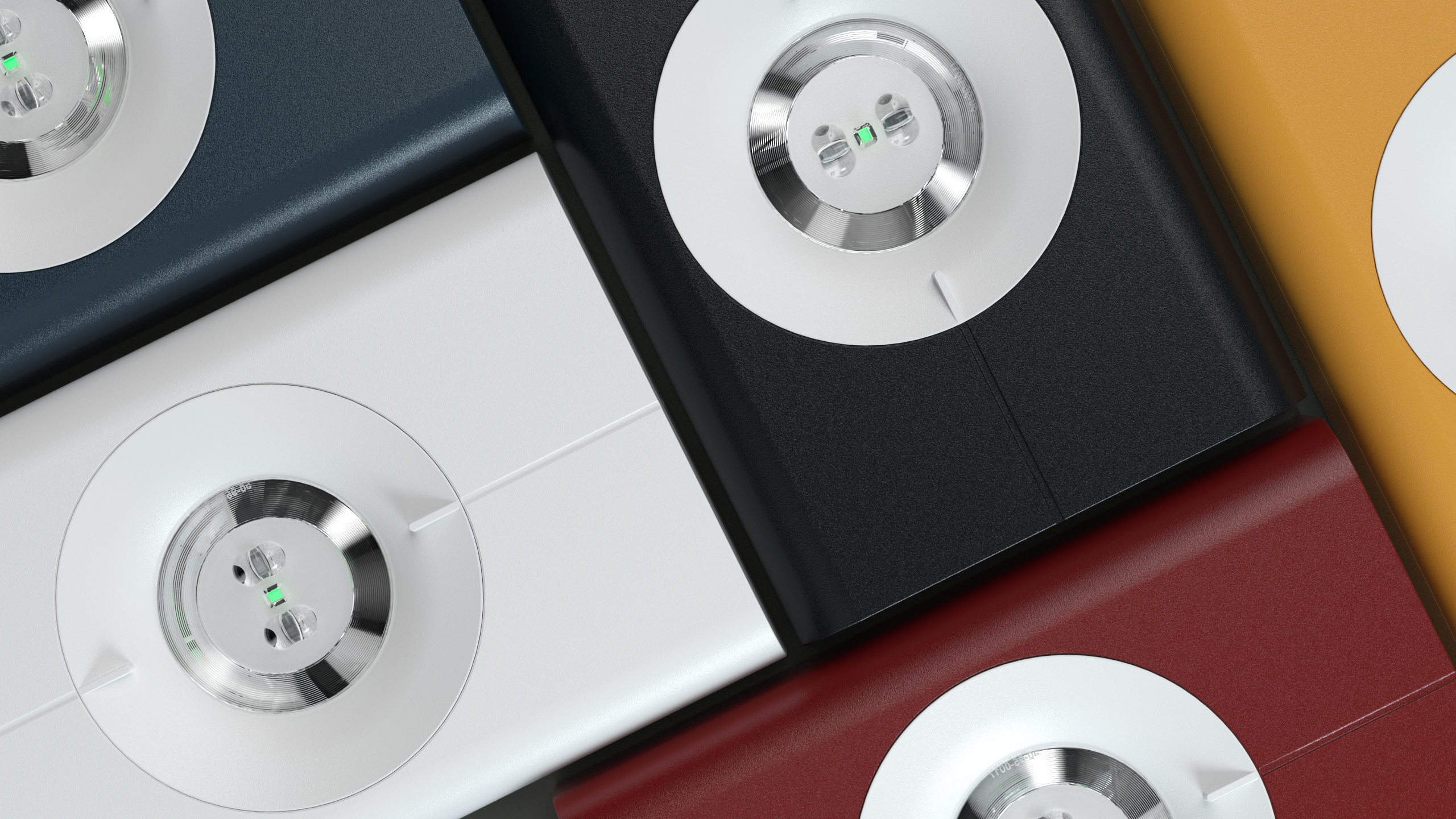
User interface and industrial design
The enclosure is usually the only part of the product the user sees and touches. Its industrial design communicates the product’s quality, purpose, and brand identity. A well-designed enclosure makes controls intuitive, status indicators visible, and labelling clear. It positions the product appropriately in its market — whether that’s a premium consumer product, a robust piece of industrial equipment, or a precision medical device.
This is another area where the enclosure design cannot be separated from the engineering. The position of controls and displays is determined by the PCB layout and the user’s ergonomic requirements. The position of cable entries is determined by the installation environment. The form factor is constrained by the electronics package and the thermal management strategy. The industrial design works within and responds to these constraints — it doesn’t override them.
At Bluefrog Design, we design custom enclosures as part of an integrated product development process that covers industrial design, engineering, prototyping, and design for manufacture. We’re based in Leicestershire and work across industrial, consumer, and medical sectors. If you need a custom enclosure designed and engineered for production, get in touch.
View more of our Product Development Services
If you would like to hear more on how we can improve the quality of your products or help with your product development, please contact Bluefrog Design at mail@bluefrogdesign.co.uk
FAQs
What is a custom electronics enclosure?
A custom electronics enclosure is a housing specifically designed and engineered to contain, protect, and support electronic components for a particular application. Unlike off-the-shelf enclosures, a custom design is developed to match the exact requirements of the electronics, the operating environment, and the user interface. This includes the internal mounting and cable routing, thermal management, IP rating, EMC shielding, and external industrial design.
When does a custom enclosure make sense over an off-the-shelf option?
A custom enclosure is typically justified when the electronics don’t fit standard form factors, when specific IP or EMC performance is required, when the product needs a distinct brand identity or user interface, when thermal management requirements are demanding, or when production volumes justify the investment in a purpose-designed solution. For very early prototypes or internal tools, off-the-shelf enclosures may be sufficient.
What materials are used for electronics enclosures?
The most common materials are sheet metal (steel or aluminium), injection moulded plastic (ABS, polycarbonate, nylon), and die-cast aluminium. The choice depends on the application requirements: EMC shielding, thermal management, IP rating, mechanical robustness, weight, and production volume. Each material has different cost and manufacturing implications.
What IP rating does my enclosure need?
The required IP rating depends on the operating environment. IP20 is suitable for indoor controlled environments. IP54 is typical for industrial settings with dust and splash water. IP65 and above are needed for outdoor, washdown, or harsh environments. IP67 is required where temporary submersion is possible. Higher IP ratings increase design complexity and cost, so specifying the right level for the application is important.
How does EMC affect enclosure design?
Electronic products sold in the UK and EU must meet EMC standards (UKCA and CE marking). The enclosure contributes to EMC compliance by shielding the electronics from external interference and preventing the electronics from radiating interference. Metal enclosures provide natural shielding when properly bonded and grounded. Plastic enclosures require additional measures such as conductive coatings or internal shielding. EMC requirements affect material choice, joint design, and cable entry points.
Can Bluefrog Design develop a custom enclosure for my electronics?
Yes. Bluefrog Design, based in Leicestershire, designs and engineers custom enclosures as part of an integrated product development process. Services cover industrial design, engineering, prototyping, and design for manufacture across industrial, consumer, and medical sectors.